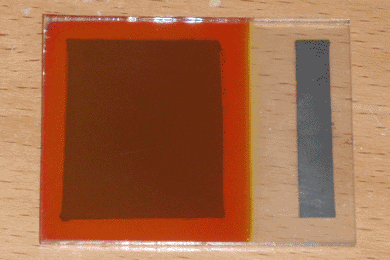
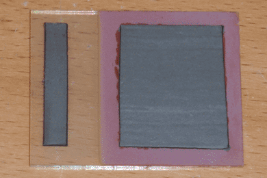
Optimization can become complex when more than two variables are involved. Due to potential interactions between variables, the naive approach is to exhaustively explore every possible combination, a task which grows exponentially as the number of variables increases, quickly becoming impossible for the home experimenter. A simpler approach is to break down a large project into components, each of which has a single primary function that can be optimized independently. Once this function is identified, the task is reduced to a series of single-variable optimizations. In the case of my solar cell design, I first identified the primary function of each layer, excluding the conductive paste contacts which had been developed earlier.
| Layer | Function |
|---|---|
| SnO2 (N-Type Conductor) | Transparency |
| ZnO (N-Type Semiconductor) | Open-Circuit Voltage |
| Cu2O (P-Type Semiconductor) | Short-Circuit Current |
| Cu2S (P-Type Conductor) | Conductivity |
Starting with the conductive tin oxide layer, I began exploring where I left off in my previous article. Further tests using antimony as a dopant in the range of 1-2% yielded highly variable results, only occasionally producing conductive glass of a high enough quality for solar cells. I believe this is possibly due to a difference in volatility between the tin and antimony chlorides, making successful deposition highly temperature-dependent. For this reason I returned to using fluorine as a dopant, using my earlier method. Ultimately, I settled on using a solution of 0.40M stannous chloride and 0.10M ammonium bifluoride in distilled water, which reliably produced a highly transparent conductive coating when sprayed on window glass at roughly 500°C. As per the original article, I found 15mL of this solution to be adequate for glass up to 3 by 3 inches in size.
Moving on to the zinc oxide semiconducting layer, I found that removing the previously-used boron dopant had little effect. Furthermore, a number of research papers indicated that adding magnesium in fairly large proportions could widen the bandgap of zinc oxide, increasing the open-circuit voltage of ZnO/Cu2O solar cells. Through experimentation I found that a solution containing 0.40M zinc acetate and 0.04M magnesium acetate in roughly 2% acetic acid produced cells with the highest voltage. Only a small amount of this solution is necessary, with roughly 5mL being needed to form a suitable coating.
The copper oxide layer required the largest time investment by far. Attempts to dope the plating solution with various impurities were universally met with failure, by either having no effect or by ruining the plating bath. During this experimentation however, I discovered a unique procedure for preparing the solution, which results in a highly transparent and moderately conductive copper oxide layer without the use of external dopants.
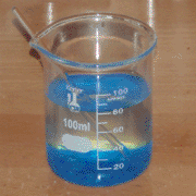
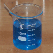
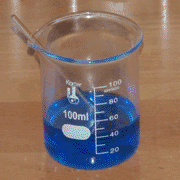
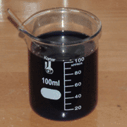
Rather than using pre-made sodium lactate as I had done previously, I began with 50mL of water and 25mL of 90% lactic acid, which I purchased from Lotioncrafter. To this I added 10 grams of copper sulfate, which dissolved very slowly with stirring and gentle heating. Once it had fully dissolved, I then raised the temperature to 80°C and let the solution evaporate down to 40mL over the course of four hours. Finally, I slowly adjusted the pH to 10 by adding 6M sodium hydroxide solution dropwise while stirring, then adjusted the volume to 100mL with distilled water. This process is documented in the pictures above. Interestingly, the solution is self-indicating; it becomes a dark blue-black at a neutral pH, then becomes slightly purple and transparent when the pH reaches 10.
The result of this procedure is a plating bath that is slightly viscous at room temperature, to the extent that pH paper will form an indentation in the liquid before breaking the surface. I believe that this is due to the evaporation process; as the copper sulfate dissolves and the copper is complexed by lactic acid, free sulfate (sulfuric acid) is formed, which is a known polymerization catalyst for lactic acid. My theory is that short-chain polylactic acid is formed in solution, which is a better complexing agent than the lactic acid monomer. Unfortunately, I have no way of verifying this. Regardless, in application this viscous plating bath has two interesting properties. First, it is extremely stable and can be boiled or frozen with no visible degradation. Second, at a temperature of 70-80°C and a current density of roughly 1-3mA/cm², it will deposit a substantially haze-free layer of transparent copper oxide, resembling red stained glass. This type of layer has no pinholes, and can be sulfided with little to no loss of open-circuit voltage. When I could produce this type of material reliably, I considered this layer completed.
Finally, the optimization of the copper sulfide layer was entirely straightforward. Dipping a cell made up of the previous three layers into a dilute solution of sodium sulfide creates a thin conductive layer of copper sulfide, the concentration of this solution being limited to roughly 0.001M. Exceeding this creates an irregular sulfide layer, which tends to flake off. The only remaining variable, then, is dipping time. Long exposure tends to create leakage paths through the copper oxide layer, and through experimentation I found that the useful range is between 1 and 10 seconds, with 3 seconds producing the optimal balance of open-circuit voltage and short-circuit current. After this process, the cell can be rinsed with tap water; distilled water could be used for tighter process control, but I haven't found this necessary.
With all of the layers optimized, I then encountered one final problem. Cells produced this way would, if exposed to sunlight for an hour or two, permanently lose roughly half of their open-circuit voltage. I determined that this was likely caused by residual water inside the cell. An additional drying step for 30 minutes at 110°C eliminated this problem, although cells produced this way still temporarily lose some voltage when exposed to light or heat. At this point the optimization was complete, so I made a number of large (1-1/2 x 2 inch) solar cells and documented the procedure in the video below. The solar cell shown in the video (and at the top of the page) has a maximum open-circuit voltage of 525mV and a maximum short-circuit current of 6.5mA, or roughly 0.9mA/cm² over an active area of 7.5cm².
As an extension of my conductive glass, this method for making solar cells is likewise simple enough for the average home experimenter to accomplish, and requires no machine tools or other expensive equipment. The cells produced this way can be used as power sources or light sensors, and are mechanically robust enough to be easily incorporated into other devices. At just over a year since I began this project, I now consider it complete. Hopefully others will be able to replicate and improve upon my work here, and bring solar power further into the realm of amateur experimentation. For now though, I will return to making simpler things.
