Trepanning consists of forming a hole by cutting out the center of a turned object. The operation is similar to parting, but requires a specialized tool due to the curvature of the cut. Industrially, curved parting tools are commonly used for this task, while amateur machinists often use hole saws. Both of these tools are limited to specific diameters, however, so I decided to take a different approach and grind a variable-diameter trepanning tool for my lathe.
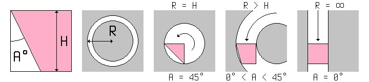
I began with a section of 1/8" square tool steel. This is the smallest that I had on hand (and the smallest that is commonly available), which is essential since the full width of the bit will be plunged into the workpiece. I then determined the necessary side relief; this enables the bit to fit inside the groove being cut, without rubbing on the outer edge. This relief angle (A) is dependent on both the height of the bit (H) and the radius of the hole (R), and can be calculated by the formula A = arcsin(H / R) / 2. The diagram below illustrates the significance of the side relief.
For the trepanning tool at the top of the page, I chose a minimum radius of 5/16", for a minimum hole diameter of 5/8". This is simply due to the fact that for holes any smaller, a drill bit is more suitable. Using the above formula, this choice of radius resulted in a relief angle of 11.8°, which I rounded up to 12°. I then used a belt sander and a small vise to grind this angle along the full length of the bit, as well as on the tip to sharpen it. The continuous cross section allows it to be sharpened indefinitely without changing shape, which has become a requirement for any cutting tool I make.
Equally important to the tool itself is the holder which supports it. The 1/8" height is too short for my lathe, which natively holds 5/16" bits on center in its toolpost; the 1/8" width is also smaller than the diameter of the toolpost bolts, which would quickly be marred if tightened down on it. To resolve these issues, I cut a groove in the side of a 5/8" square section of mild steel, then drilled and tapped holes on the top for #6-32 set screws, which I made from stainless steel threaded rod. The design is essentially a linear version of my boring bar, and provides both clamping and alignment for the small trepanning bit held inside. By using such a holder, the overhang of the cutting bit can be reduced to the minimum necessary for the cut being made, which is essential due to the high cutting forces involved.
Tests of this bit and holder had very interesting results. Surprisingly, my small lathe was capable of cleanly trepanning alloy steel (effectively removing 1/4" from the diameter in one pass) as long as cutting oil (in my case, castor oil) was used, and the feed rate kept high to avoid chatter. This removed a smooth ribbon of metal, and that quality of cut could be maintained until the tool overhang exceeded 1/4", at which point the chatter became uncontrollable. Still, a quarter-inch depth of cut is far beyond what I expected under those conditions, and implies that half-inch steel plate could be successfully trepanned (producing an equally thick center disc) if both sides were accessible. The calculated minimum radius held true as well; a test cut just short of this radius started cleanly, but then began to jam as the cut became deeper. This test piece, along with the trepanning tool and its holder, can be seen at the top of the page.
Overall, I am highly pleased with this design, and the only improvement left to be made is to minimize the cutter width, so that less power is required to make the cut. This would be a trade-off with rigidity and chip clearance, however, and would likely require a different holder design, perhaps similar to that of a parting tool. I will explore this option if necessary, but for now the current tool appears to be adequate for the tasks that require it.