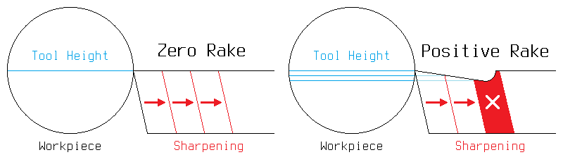
As I have continued to refine my metalworking techniques, I have found that for general-purpose work on a small lathe, cutting tools without back rake are preferable. They are easy to make, easy to sharpen, and have no tendency to pull themselves into the workpiece. Furthermore, since they contain no concave surfaces, they can be resharpened indefinitely without changing shape, much like a pencil. The diagram below illustrates this principle; while a zero rake tool can be sharpened down to a stub, a positive rake tool always contains some amount of waste material which must be ground away to restart the cutting edge, and throughout this sharpening process the tool height will constantly change.
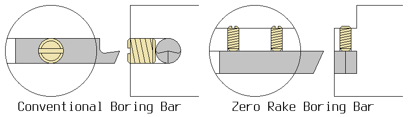
This principle is readily applied to external cutting tools that are held in the toolpost; however, for internal cutting tools, a special boring bar must be made. Typically, boring bars are made by drilling a cross-hole through a stiff steel bar, to hold a smaller rod of tool steel that is sharpened into a cutting bit. This sharpening necessitates removing the top half of the rod, followed by further metal removal for the clearance and rake angles. The result is a fragile cutting tool that is essentially unsharpenable. Alternatively, if a boring bar is made with a slot milled across the face, it can hold an ordinary zero rake cutting bit with a square cross section. A comparison of these two types of boring bars can be seen in the diagram below.
This boring bar design is highly adaptable, and can be adjusted as needed for the shape and size of the work that requires it. The bar at the top of the page has its face skewed 30 degrees, allowing it to perform either turning or threading operations, depending on the bit. The bits it holds are an eighth of an inch square, and the bar itself is half an inch in diameter; this 1:4 ratio appears to be the maximum bit size that is reasonable without sacrificing rigidity. Its diameter allows it to be used directly in a boring head on my milling machine, or on a pillow block in the toolpost of my lathe; however, as mentioned above, it was designed with a specific purpose in mind: to form the sockets in my die holder.
The above boring bar, although perfectly suited to internal turning tasks, is less ideal for threading than I anticipated, due to the lack of side clearence when used to cut 60-degree threads. For this reason I made another boring bar for internal threading, which has no built-in cutter angle. This new bar can also be clamped along its full length, enabling the overhang to be minimized by retracting the bar into the toolpost. These improvements can be seen below.