|
|
|---|
Of all available sources of energy on earth, the light of the sun is the most ubiquitous; however, as a source of heat it is somewhat difficult to utilize due to its diffuse nature. Direct sunlight provides roughly a kilowatt of power to every square meter of an illuminated surface, but without some method of containing this energy, the vast majority of it is either reflected, carried away by convection, or re-emitted as infrared radiation. It follows then, that if these losses could be mitigated and a sensitive thermocouple were used to convert the trapped heat into electricity, a solar panel could be made which requires no complex materials or construction methods to manufacture.
Naturally, this is not a new idea; thermoelectric solar panels were developed throughout much of the early 20th century, most notably by pioneers George Cove (in the 1900s) and Maria Telkes (in the 1930s). However, almost all of these devices utilized the semiconductor zinc antimonide (ZnSb), due to its exceptional thermoelectric performance when compared to metallic alloys. Unfortunately, this level of performance comes with a variety of severe issues which make it impractical for the task at hand: First, it oxidizes rapidly when molten, producing poisonous smoke and leaving oxide inclusions in the resulting castings. These castings then (even when free of oxides) possess little tensile strength and expand as they solidify, causing them to self-destruct. Furthermore, the molten compound inevitably soaks into porous graphite equipment (e.g. crucibles and stirring rods), destroying these items upon cooling as well. Finally, if an intact casting is somehow produced (historically by casting under vacuum into a heated mold), it is still essentially non-machinable and vulnerable to corrosion and mechanical stress. It is likely for these reasons that few surviving thermoelectric devices exist which used this material, which is why I developed my bismuth alloys for this purpose instead.
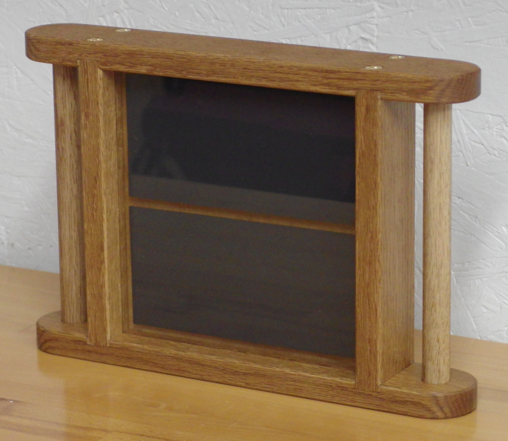
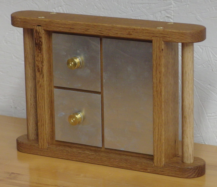
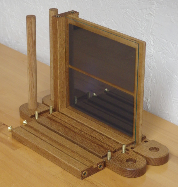
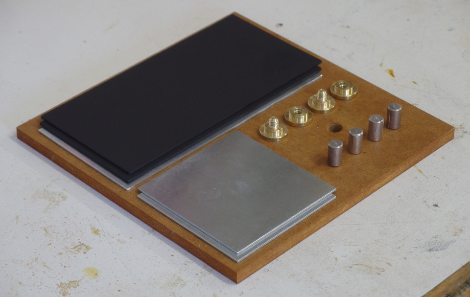
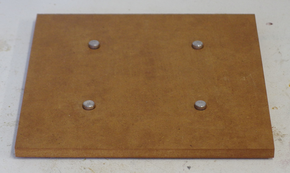
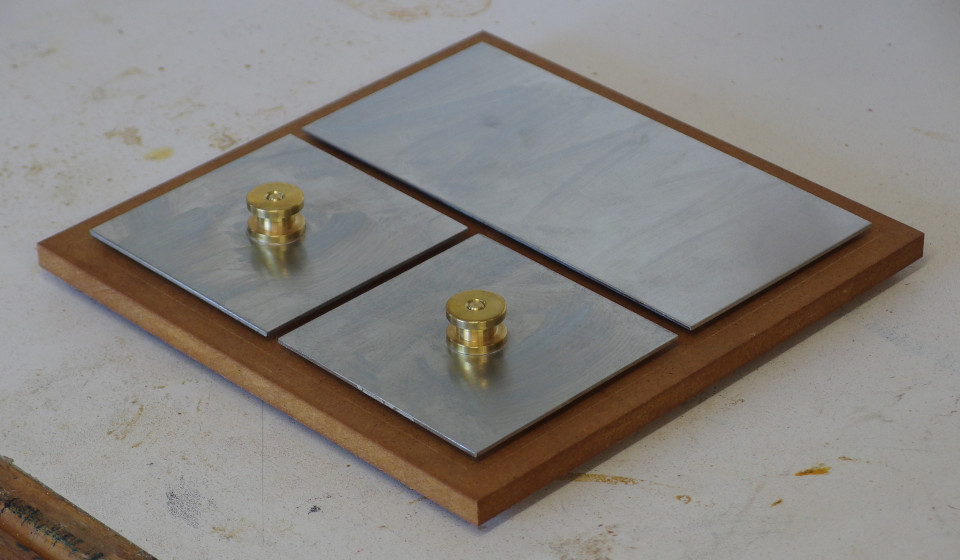
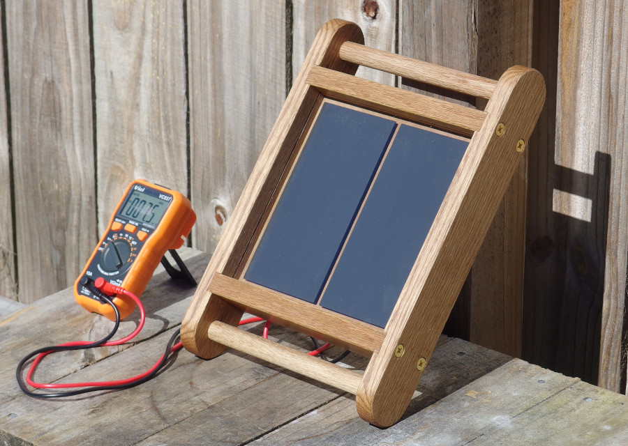
Having identified a suitable thermocouple, the next task was to design a solar absorber to collect sunlight and convert it into usable heat. Fundamentally, this consists of a blackened plate of metal centered inside of a sealed enclosure (to limit conduction and convection losses) with a pane of glass on the sun-facing side (to admit visible light and contain infrared re-emission). In this panel, the plates are made of painted zinc sheet, which achieves a suitable balance of cost, conductivity, and solderability. The paint itself is simply black iron oxide mulled with concentrated sodium silicate as a binder; this bonds well with zinc, and becomes water-resistant when baked at 150°C. These plates, along with equally-sized radiator plates (to conduct waste heat to the surrounding air) were then soldered (using eutectic tin-bismuth solder) to alternating positive and negative bismuth alloy legs, which had been pressed through holes in a sheet of fiberboard. This assembled core was then mounted in a wooden frame made of red oak, which I first stained via ammonia fuming, then finished with a wiping varnish made by mixing boiled linseed oil and tung oil varnish, followed by polishing with beeswax paste. The resulting solar panel can be seen at the top of the page, and the assembly process of its core can be seen below.
|
|---|
Of key importance in the design of such a panel are its mechanical dimensions; specifically, the size of the air gap surrounding the absorber plates, the thickness of the plates themselves, the length of the alloy legs, and the ratio of the cross-sectional area of the legs to the sun-facing area of the absorbers. While it is theoretically possible to model the interaction of these variables, their interdependency makes this difficult to achieve with any degree of accuracy. Ultimately, I decided to design the panel with an interchangeable core, to allow it to be optimized empirically instead. As a starting point, I chose a design where the plates are 1/16th of an inch thick and surrounded by roughly 1/8th of an inch of air, with alloy legs 5/8-inch long and 3/8-inch in diameter, and with a plate-to-leg area ratio of roughly 100 to 1. This intentionally makes the air gap somewhat small and the area ratio somewhat high, so that future adjustments only need to be made in one direction to determine the point of diminishing returns. The resulting panel has an internal resistance of 3 milliohms, and produces up to 7.5 millivolts in direct sunlight at an ambient temperature of 10-15°C, as seen below. With an active surface area of 0.033 square meters and a maximum output power of 5 milliwatts (to a 3 milliohm load), this corresponds to an efficiency of roughly 0.01%, which is comparable to some of the results from my early photovoltaic cells.
|
|---|
Overall, this solar panel is highly unoptimized, and is essentially a first draft and a proof of concept. Aside from adjusting the critical dimensions however, its component materials can also be improved. Most obviously the perforated fiberboard sheet is unsuitable for long-term use outdoors, and could realistically be replaced by either solid wood or some type of insulating cement composite. This sheet could also be painted with a thermally-reflective (e.g. aluminum-pigmented) paint to improve its insulative properties. The absorber paint could also be improved, as it has a tendency to form an efflorescent coating of sodium carbonate when exposed to high humidity, and iron oxide is likely not the most efficient pigment for its purpose. Finally, the tin-bismuth solder could be exchanged for a tin-lead-bismuth eutectic alloy (melting at 95°C), since this forms anyways via diffusion at the negative alloy legs, and would enable the reflow-soldering of an entire core at once, even with a hydrated material (e.g. wood, cement, or plaster) as the perforated sheet. Furthermore, this leaded eutectic is ductile, which would improve the overall durability of the panel, assuming it can be designed to never reach 95°C internally.
Ultimately though, this type of solar panel is fundamentally limited by the thermoelectric properties of the alloys used within it. Assuming it is eventually possible to achieve a temperature differential of 50°C across optimally-sized plates and thermocouples at a thermal efficiency of 50% (reasonable estimates for a flat panel absorber of this type), the output efficiency would be limited to roughly 0.25%, or 2.5 watts per square meter of panel area. This is clearly insufficient for this type of panel to be used as a primary source of electricity, especially considering the relative scarcity of bismuth. On the other hand, if such a panel were designed to charge a small battery, it could be used to operate communications equipment in remote locations with little to no maintenance. This niche is relatively important, since most other uses for electricity (light, heat, motion, etc.) can be achieved by other means. Constructing such a panel would require significant improvements to the manufacturing process however, due to the low voltages produced by the thermocouples. Even at maximum efficiency, hundreds of alloy legs would be required per volt of output. This is still within the realm of possibility though, and I intend to describe such a panel in a future article if no alternative device can be developed in the meantime. Overall I am happy with the results of this project, as it serves to decouple solar electricity from the necessity of semiconductors; however, since the limitations of thermoelectric materials have now become fairly apparent, I plan to move on to other fields of experimentation for the time being.