
The making of gears is viewed by many amateur machinists as a daunting task, one requiring advanced mathematics, expensive cutting tools, and a dictionary of specific nomenclature. All of this is unnecessary, however; cutting gears on a mill is no more difficult than cutting threads on a lathe, and in fact, the same cutting tool can accomplish both tasks.
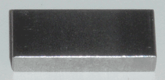
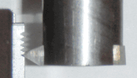
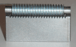
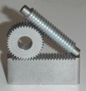
To illustrate this principle, I began by making another boring bar, this time 3/4" in diameter, which holds a 3/16" square tool bit. This bit is ground identically to a threading tool, and has a 60° included angle. Held in a collet, the boring bar becomes a gear cutter, and can cut triangular teeth in horizontal passes. To make a rack, the simplest type of gear, this cutter is simply passed across a straight piece of stock in regular vertical intervals. The depth of cut can be determined by eye (as in threading), but for 60° teeth it will always be 86.6% of the tooth width. This width (inches per tooth) is the inverse of the pitch (teeth per inch), so for the 20TPI rack shown below, the tooth width is 0.050" (1" / 20), and the tooth depth is 0.043" (0.050" * 0.866). In the picture furthest right, I have included a 1/4-20 threaded rod to illustrate the similarity; the two components mesh perfectly.
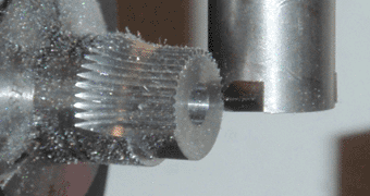
While the example above is trivial, the principle is general; a spur gear is simply a rack wrapped around a circle, so the same calculations apply. The tooth width can be calculated by dividing the pitch circumference by the number of teeth, and the depth of cut determined just as above. For gears having over 20 teeth, the curvature per tooth is negligable, so the teeth can be cut straight. The 40-tooth gear below has a pitch diameter (measured at the midpoint of the teeth) of 0.625"; this corresponds to a tooth width of 0.049" (0.625" * pi / 40) and a tooth depth of 0.043" (0.049" * 0.866), this depth being added to the pitch diameter to determine the outer diameter of the gear blank (0.668"). This tooth size will be the same for any gear of a matching diametral pitch (64 teeth per inch of pitch diameter), and interestingly it is close enough to that of the previously made rack to mesh smoothly with it. The process of making this gear can be seen below.
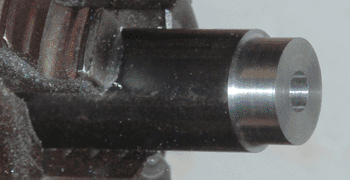
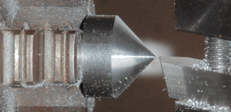
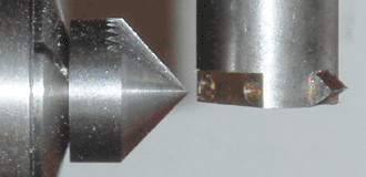
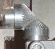
Surprisingly, this method can be extended even further. By converting both the step between teeth and the tooth depth to angular values, a conical gear can be made. This can be explained by the fact that a conical gear is simply a spur gear projected from the center of a sphere onto its inner surface. The width of this projection (the pitch diameter) is measured as an arc across the surface of this sphere, and can be expressed in degrees. The 36-tooth conical gear shown below has a pitch diameter of 90°, a tooth width of 7.85° (90° * pi / 36), and a tooth depth of 6.80° (7.85° * 0.866). The cone blank has an included angle of 96.80° (90° + 6.80°), and the teeth were machined by mounting the indexer at 41.60° (45° - 6.80° / 2) relative to the table with a vernier protractor, and advancing the cutter depth in shallow passes until it just reached the tip of the cone. A pair of these gears mesh smoothly at an exact right angle, confirming the validity of the calculations.
The above method will suffice for a wide variety of situations where gears are needed; however, two exceptions may be encountered, both of which have straightforward solutions. The first exception is for gears with a small number of teeth: in this case, interpolating cuts must be made on either side of the initial tooth valley, to round the tooth profile and eliminate flats on the outer diameter. These cuts should be made at fractional tooth positions, and the depth of cut should be reduced by twice that proportion; for example, a cut at +/- 1/4 of a tooth would be at 1/2 of the tooth depth (measured in degrees for conical gears). This can be thought of as the cutter riding over the peaks and valleys of the gear teeth as the gear rotates. This applies to all gears except racks, and in general the fewer teeth a gear has, the more interpolating cuts need to be made to achieve a sufficiently smooth tooth profile.
The second exception is if a tooth angle other than 60° is desired. In this case, the tooth depth (ordinarily 86.6% of the tooth width) can be calculated by dividing the width by 2 * tan(A / 2), where A is the included angle of the cutting tool. The tangent function converts an angle to a slope (rise over run), and two slopes back-to-back define the cutting tool geometry.
One last detail to note is that this method produces gears (with the exception of racks) that are slightly oversized, due to the nature of forming a curved shape with a straight tool. Even with interpolation, microscopic crests are left between the facets formed by the cutter, and these cause the gears to have a slightly larger than nominal pitch diameter. These crests can be eliminated by wearing in the gears with an abrasive paste, but if this process is undesirable or if perfectly smooth gears are unnecessary, the depth of cut can be increased (equally for all cuts) to provide adequate clearance. In general, once the original surface of the gear blank has been totally machined away, the gear will mesh freely at the expected distance, albeit with some roughness.
Overall, I believe this method is robust enough to produce gears for the majority of applications in which an amateur machinist would need them. The triangular tooth profile has its weaknesses (fragility at the tooth tips, high pressure angle), but as with triangular threads, geometric simplicity and ease of manufacture generally outweigh these faults. Future projects will test this type of gear more thoroughly under various conditions of size, speed, and load, and any necessary modifications to this process will be recorded here.