As of two weeks since its construction, the previous triode is still functional. With the long-term viability of a titanium getter confirmed, I decided to build another tube. This triode uses a section of 10mm titanium tubing as the plate, which doubles as the getter. This not only increases plate current by more effectively collecting the electrons emitted from the filament, but it also greatly improves the level of vacuum in the tube. This triode did not need the extensive daily gettering process that the previous triode required, and in fact was completely stable after one day.
Due to the large amount of getter material to be heated, I decided to use a bulb-shaped envelope for this tube to avoid having the glass crack during the gettering process. Judging by the high temperature of the glass after heating the getter with my induction heater, I believe this was the correct choice, although I will experiment with straight envelopes in the future. To form the bulb, I first made long, 4-inch envelopes using the usual process, then made a mandrel to allow me to heat and inflate the envelopes on the lathe.
In the back of the mandrel is a ball bearing mounted on a short length of quarter-inch copper tubing, which extends out of the back of the lathe. A rubber hose can be attached to this tubing to allow air to be blown into the envelope. The ball bearing allows the mandrel to spin without spinning the blow-hose. In the process of inflating the envelope, the tip was closed while the envelope was shaped, then blown open again at the end. This produced a fairly messy opening, so perhaps in the future a better method could be developed. Finally, the envelope was scored and the excess tubing was broken off. This excess was necessary, otherwise the heat would be too close to the plastic mandrel.
Once a batch of these envelopes was produced, I then assembled the internal structure of the triode. The pinch seal was made in the same method as the previous triode, with nickel leads for flexibility and solderability. The key differences are in the grid and the plate. The plate was made from seamless titanium tubing as previously mentioned, and the grid was made from 0.5mm nickel wire wound into a spring. I chose to use nickel because it is extremely soft and does not spring back when formed into a coil. Another minor difference is the use of a slightly smaller (0.08mm) filament.
Once the internal structure was complete, I soaked it in acetone to remove any grease or fingerprints, then let it dry. I then attached an evacuation stem to the bulb envelope and sealed in the electrode assembly. Once the tube had cooled, I evacuated it to 10 millitorr and baked it out for an hour at 50W. I then let it cool in the oven for a half hour. At that point, I lit the filament to drive out any trapped air, heated the plate with my induction heater, and sealed the tube. I then heated the plate again to an orange heat, and once it cooled down I took some initial measurements. Over the next two days I continued to take measurements, and the tube remained stable throughout this time period. I then recorded the tube's characteristics, starting with its grid response curves at various filament settings.
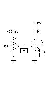
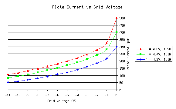
The two major problems here are the non-linearity (the bend at -1V) and the remote cutoff (beyond -11V). Both of these, I believe, are caused by the grid being physically too short. There is a section of filament with an unobstructed line of sight to the plate at the top of the tube. The emission at this section is therefore difficult to control via the grid. No matter what, these electrons pass from filament to plate. The majority of the electrons are emitted within the grid coil, though, and due to the tight spacing of the coil, they can be modulated very easily (the steep portion of the curve near 0V). I believe the grid is actually spaced too tightly, however; when the grid is tied to the plate, the tube can easily conduct 10mA. When the grid is tied to ground, plate current can barely exceed 500µA. Future tubes will use thinner wire and a wider spacing.
One benefit of the tight grid spacing is high transconductance, however. Within the steep region, transconductance reaches 170 µmhos, and this is utilized in the following amplifier circuit. As usual, the input is a 10KHz sine wave.
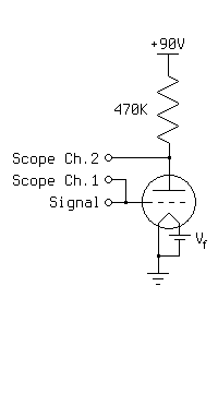
Due to the output signal being viewed in AC mode, the two signals are overlaid. The smaller signal is the input, at 0.5V per division. The larger signal is the output, at 10V per division. This means that a 0.8V input is turned into a 28V output, yielding a voltage gain of 35. This amplifier was difficult to get to operate linearly, though, and it required the input to be unbiased to avoid the bend at -1V.
Despite having a few flaws, the design of this tube seems to be sound, and in the future I plan to make an improved version of this triode for use in an audio amplifier. Before that, though, I have some other projects in mind.