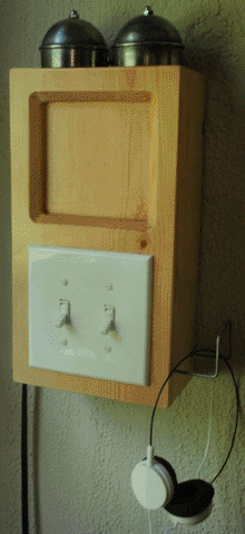
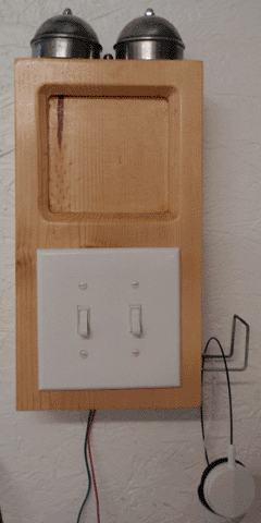
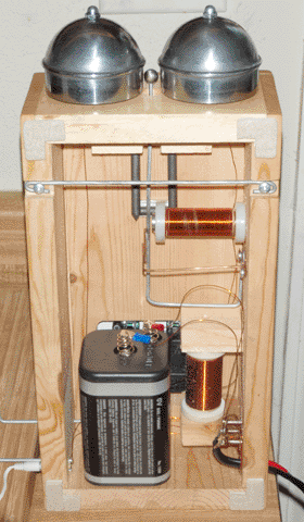
To expand upon the carbon microphone in the previous article, I built a set of telephones to connect my house and my workshop. All of the components are homemade, except for the switches on the front panel. Specifically, for each phone I built a bell mechanism, a microphone, and an audio transformer, all of which I will describe in detail below.
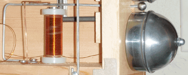
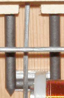
The bell mechanism is fairly simple. Two fence post caps are mounted on threaded rods on top of the telephone as bells, and a ball bearing mounted on a thick steel wire acts as the hammer. The wire is pulled by an electromagnet, the power to which is interrupted by a copper contact behind the coil. With some adjustment, the ball bearing will oscillate between the two bells, producing a ring that is very similar to that of an old rotary-dial telephone. The coil itself is made from 540 turns of 24 AWG magnet wire, wrapped around a 3 inch length of half-inch steel rod. I initially intended for the bell to operate on 1.5 volts, due to this being the optimal voltage for the carbon microphone. This proved to be unrealistic, however; especially considering that the power to one telephone's bell had to come from the other telephone, over the 50 feet of wire separate the two. Due to this, I decided to make the telephones operate on 6 volts from a lantern battery.
Due to the higher voltage needed for the bell, the microphone needed to be specially designed. Operating the previous microphone at 6 volts invariably caused arcing and oscillation, which completely drowned out any speech. To overcome this, I split the voltage by putting two carbon contacts in series. This had the positive side effect of making the connections simpler (no need to run a wire to the center of the diaphragm), but the negative effect of reducing the sound quality. This was due to the fact that each contact receives 2-3 volts, which is still too high, and also because adding contacts in series increases the likelihood of the contacts breaking up from loud speech. With some fine tuning, however, the quality could be made acceptable for a telephone. The larger diaphragm (4-1/4 inches across) also complicated things by making the microphone far too sensitive. This was overcome by putting the middle carbon off-center.
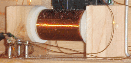
An audio transformer was necessary to remove the large DC component of the audio signal and to provide some crude impedance matching, so that ordinary headphones could be used as a receiver. I made such a transformer by packing a short length of 1/2 inch (nominal, the actual diameter is around 7/8 of an inch) PVC pipe with 14 AWG soft iron wire, and wrapping it with two coils of magnet wire. The primary coil is 180 turns of 24 AWG wire, and the secondary is 1800 turns of 32 AWG wire. I chose a linear core design due to the large DC current through the primary, and because such a core is straightforward to make.
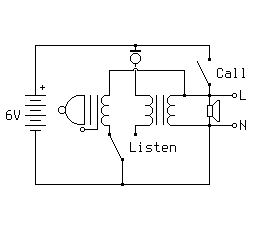
The circuit for each telephone is quite simple. One switch enables either the bell or the microphone, by connecting one of the two to ground. The other switch puts 6 volts on the line output, which runs the other telephone's bell. There are some downsides to this design, however. First, if the microphone is not enabled before attempting to ring the bell, you will ring both bells. Second, the receivers are connected to the line at all times, including when the bell is being rung. If you are wearing the headphones and the person on the other end accidentally rings the bell, you will hear a loud popping sound. Third, and relatedly, when either bell is rung, both sets of headphones are briefly exposed to 6 volts DC. This is far beyond their operating limits, but they seem to tolerate it well.
A demonstration of the telephones in use can be seen below. Note that the audio amplifier I made previously is being used as a speakerphone, indicating that the triode inside of it is still functional. The sound level from the amplifier is very low due to the headphones pulling down the transformer output. I initially intended for the receivers to be piezoelectric, so the secondary of the transformer has an impedance greater than 100 ohms; however, both pairs of headphones have a combined impedance of 8 ohms. This is grossly inefficient. In the future I will most likely wire the left and right channels of the headphones in series rather than parallel, to increase the combined impedance of both sets to 32 ohms.