The electrolytic rectifier operates on the principle that an aluminum electrode in an electrolyte will only conduct when it is negatively charged. When it is positively charged, it quickly forms an insulating layer of aluminum oxide which prevents further current flow. When it is negatively charged, it forms hydrogen at the surface of the electrode, which disturbs the oxide layer enough to allow current to flow. I first encountered this type of rectifier in an article by Nyle Steiner, but noticed some potential improvements to be made. Namely, I believed I could combine two rectifiers in one jar to make a full-wave rectifier, and I also believed that I could reduce the parasitic capacitance by using electrodes with less surface area. Both goals were accomplished.
I started by making the electrodes; the outer two are made from aluminum, and the center one is made from steel. All three are 0.25 inches in diameter, 2.25 inches long, and are tapped to receive a #10-24 screw at the top so that a ring terminal can be attached. They are press-fit into the lid, which is made from poplar, and the bottom half (not visible) is tapered so it fits in the jar like a cork. A vent hole was drilled through the lid as well, so that pressure does not build up within jar during operation. The jar itself is a spice jar, and is about 2 inches in diameter and 2 inches tall. Once the components were assembled, I filled the jar about 3/4 of the way with hot water and added 1/4 of a teaspoon of baking soda. Once the baking soda had dissolved, I began testing the rectifier using the circuit below.
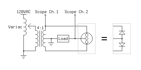
Before turning on the oscilloscope, I tested the rectifier qualitatively by connecting a small DC motor as the load. It worked immediately, with no change in speed over time. I then switched out the motor for a 5W 100 ohm resistor, and observed the behavior of the rectifier on the oscilloscope as I varied the input voltage with the variac. The AC signal is one phase of the input, and the rippled DC signal is the voltage across the load. The load voltage is inverted for ease of understanding; it is actually negative relative to the center tap of the transformer. In all of the following images, the vertical scale is 10V per division.
I also connected a 330 ohm resistor as the load, with nearly identical results. This rectifier seems to have a voltage drop of 5-10 volts, and by testing the short circuit current I found the internal resistance to be around 10-20 ohms. I tested the leakage current between the aluminum electrodes as well, and it was under 1mA at 30 volts. Finally, I tested the parasitic capacitance and found it to be around 100-200nF.
Overall, this rectifier performed well, and after two hours of testing there was no noticeable degradation of the electrodes or the electrolyte. Although there was bubbling at the electrodes during operation, the electrolyte level was not noticeably lower than when I first filled it. The internal resistance and voltage drop could probably be improved by increasing the concentration of the baking soda in the electrolyte and by placing the electrodes closer together, or perhaps by having the two aluminum electrodes surrounded by a cylindrical steel electrode.
Interestingly, throughout the testing I never observed the glow reported by Mr. Steiner, even when I applied 120VAC directly to the two aluminum electrodes. Perhaps the glow only occurs when the parasitic capacitance is very large.