I had initially planned to use the tetrode described in the previous article to build a small AM radio transmitter. However, the plate current was too low to be useful, and could not be improved without either increasing the size of the tube (not yet possible) or increasing the complexity (undesirable). After doing research and rethinking my plans, I have decided to build the transmitter using a triode instead. For this purpose I built another power triode, which is superior to the previous one in all aspects.
I built the triode in the usual manner, using 10mm titanium tubing for the plate, 0.08mm tungsten wire for the filament, 0.5mm tungsten for the feedthrough seals, and 0.8mm nickel wire for everything else. One change I made for this particular tube was to have the filament take the shape of an inverted V, suspended by a hook at the top. This increased filament length is the source of this tube's greater emission, which can now be achieved at a modest filament current of 1 amp. The hook also serves to tension the filament, eliminating the possibility of it shorting to the grid as it expands with heat. This had happened in a few previous tubes, and it was always disappointing. Another experimental change was the use of the pinch seal to hold a structural element. The base of the tensioning hook is pinched in the center of the feedthrough area, but does not have an external connection. It seems to be held firmly in place, so although nickel cannot make an airtight seal in Pyrex it appears to at least be mechanically sound.
After the tube was assembled and evacuated, I began testing it. Like the previous tube, it immediately became gassy and required a second heat of the getter. Since this tube used a previously-tested filament size which had not caused problems in the past, I suspect the gas may have been trapped in the bubbles around the nickel wire in the pinch seal. Regardless of the source, the gas was consumed quickly by the titanium plate and the tube became functional again. The characteristic curves at various grid voltages are recorded below, with the filament set to 7.4 volts at 1.0 amps. The specific grid voltage for each curve is marked at the end of the curve in the upper right. I wanted to test this triode at higher voltages than usual, so the plate voltage was generated by rectifying and filtering the output of my variac. This is the cause of the irregularities in the graph below; I used a small analog multimeter to check the plate voltage as I adjusted it, which appears to have been a fairly imprecise method.
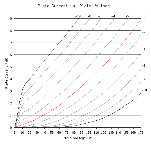
Along with the plate current, I also measured the grid current at various settings of grid and plate voltages. With +10V on the grid, the current was lower than I expected; at 0V on the plate it was 3.5mA, but as plate voltages became reasonable (>20V) the grid current leveled off to around 1.5mA. More interestingly, at negative grid voltages the grid current could not be measured. The most I could observe was a small motion of the needle on a large-dial 50µA ammeter, indicating a current of far less than one microamp, even at plate currents above 16mA. This ratio indicates that the level of vacuum inside the tube is exceptional, since any positive gas ions would have been picked up by the negative grid.
I believe this triode is the best that I have built. The electrical characteristics are within the realm of being legitimately useful, and the mechanical structure is sound. If it performs well in my upcoming radio transmitter project, I will likely replicate it for use in other projects in the future.