

Further research and experimentation revealed that the poor dye adsorption in the previous cell was caused by the low surface area of the anode. I used titanium dioxide with a particle size of 300nm, but typically a particle size of 25nm is required for this sort of device. Unfortunately, such a material is expensive and difficult to synthesize, so I decided to use tin oxide as a substitute. After a number of failed attempts to synthesize tin oxide nanoparticles, I found a research paper (DOI: 10.1039/b501579k) that described a much simpler method. Essentially, the method consists of electrolysing a dilute solution of stannous chloride, so that the oxygen produced at the anode reacts with the solution to form tin oxide at the interface between the bubbles and the liquid. Over time, this results in a porous film with an extremely high surface area. Moreover, it does this without requiring any additional ingredients beyond what was used to make the conductive glass.
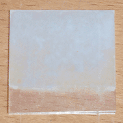
I began by cutting a 1 by 1 inch square of conductive glass, and cleaning it thoroughly to remove any oil or fingerprints. I then added 1.69g of tin (II) chloride dihydrate to 50mL of distilled water to form a 0.15M solution, and added a few drops of hydrochloric acid to clarify it. I then connected the positive end of my DC power supply to the conductive glass, the negative end to a piece of lead-free solder, and put both electrodes into the solution. Once they were in place I turned on the supply, set it to 4.5 volts, and left it running for 20 minutes. When I returned, the conductive glass had become hazy and white. I turned off the supply, removed the glass from the solution, and rinsed it with water and isopropanol. The resulting blank anode can be seen at the top left of the page.
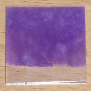
With the anode prepared, I then dyed it with blackberry juice. I began by simply laying the anode face-down in crushed blackberries for 30 minutes, then rinsing it with water and isopropanol. This worked, but left some areas weakly dyed. I then diluted the berry paste with a few milliliters of water and re-dyed the cell for another 30 minutes, rinsing it again afterwards. The results can be seen at the top of the page. The tin oxide seems to a collect a much larger amount of dye than the titanium dioxide used previously, indicating a larger surface area inside the anode.
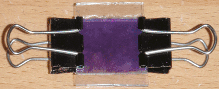
I then constructed a solar cell using the dyed anode in the same method as the previous cell. The only difference being that I filled in the back electrode with #2 pencil lead, since I found this performed slightly better than the micronized graphite I used earlier. I then let the cell sit overnight, and tested it in sunlight the next afternoon. In full sun, the cell has an open-circuit voltage of approximately 320mV, and a short-circuit current of approximately 8µA. The voltage improvement is noteworthy, indicating that tin oxide is a viable substitute for titanium dioxide; the current on the other hand is somewhat disappointing. Even taking into account the different size of the two devices, this cell still only produces 30% of the current that the first one did, and both cells are still far too weak and unstable to be of any use. Regardless, I believe the use of tin oxide in the anode is a step in the right direction, and greatly simplifies the cell design and material requirements. I will continue experimenting with this design, mainly attempting to improve the short-circuit current and dyeing method.
Replaced the research paper link with its DOI, for easier use and greater reliability.