
The conductive glass described in the previous articles was designed to be used as the front contact of a solar cell. I initially experimented with thin-film cells based on selenium and copper oxide, but achieved little success due to the coarse nature of my tools and the delicate nature of such devices. I then decided to shift my focus towards dye-sensitized solar cells. Early on I had discounted this type of cell due to its low efficiency and short lifespan, but the macroscopic nature of its components had become appealing, and upon further investigation its shortcomings were not as severe as I had initially estimated.
A dye-sensitized cell has four essential components, all sandwiched between two layers of conductive glass. Starting from the front of the cell, the first layer is the anode. This is typically a sintered, semi-transparent sponge of an n-type semiconductor, usually titanium dioxide. The next layer is the dye, which is a light-absorbing compound that bonds to the porous surface of the anode. In the center of the cell is an electrolyte, which contains ions or complexes that are oxidized by the dye in response to light. Finally, the rear-most layer is the cathode, made of a catalytic material such as carbon or platinum, which reduces the electrolyte and allows current to flow continuously. In this first attempt to build a cell I chose common, well-documented materials for all four components. This was to eliminate as many variables as possible, to ensure that I would be able to build a working cell in the first place.
For the anode of this cell, I began with a 1.5 by 1.5 inch square of my conductive glass. I then used scotch tape to mask off three sides of the glass. Next I applied a thin layer of titanium dioxide paste by wiping a razor across the taped edges. The paste was made of 300nm anatase powder, white vinegar, and a drop of dish soap. I then removed the tape and let the anode dry in the sun. After 20 minutes or so, I put it on my graphite hot plate and sintered the titanium dioxide at 450°C for 15 minutes. The hot plate and the anode were then allowed to cool naturally for a half hour.
The dye I chose was anthocyanin, commonly found in blackberries. To prepare it I simply crushed three blackberries into a paste, which I then diluted with water to decrease the viscosity. I then took the sintered anode and placed it face-down in the paste, and let it sit for two hours. After this time, the anode was only slightly dyed, being a lavender color rather than the dark purple I expected. I decided to use it anyways, but noted the potential for improvement. Finally, I rinsed the anode with water, followed by isopropanol.
For the electrolyte, I used a solution of potassium iodide (KI) and iodine (I2) in water, known medically as Lugol's iodine. I started with 1mL of a 5% solution, which I then diluted to 10mL with distilled water. This corresponds to a final concentration of about 0.06M KI and 0.02M I2. I put a layer of tissue paper over the dry anode as a separator, and added drops of the solution until it was saturated.
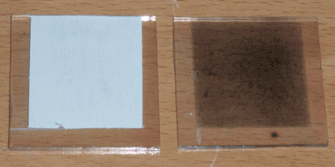
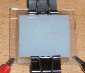
Finally, for the cathode, I began with an identical piece of glass to that of the anode, and masked it with tape in the same manner. Common catalysts for this type of cell are usually either candle soot or pencil lead, but I chose instead to rub the unmasked area with micronized graphite on a paper towel. I doubted the conductivity of soot, and pencil leads contain various clays and additives that I feared would interfere with the cell's function. With the final component completed, I laid the cathode on the soaked separator paper, and held the cell together with binder clips. The anode, the cathode, and the completed cell can all be seen at the top of the page.
The cell responded to light from the start, but initially only produced a few millivolts in room light. As the electrolyte soaked in, however, this improved to around 20mV. The current improved likewise, from 1.5 to 3.0µA. Under a bright LED, the voltage rose to nearly 140mV and the current to around 50µA. By this time it was dark outside, so I let the cell sit overnight. When I returned in the morning the cell was performing poorly, and I noticed it had dried out. After dropping water along the edges to rehydrate it, it recovered its earlier performance, so I tested it outside. In full sunlight, it produced an open-circuit voltage of 180mV, and a short-circuit current of 70µA.
This cell is obviously not useful, but it serves as a starting point for future devices. The next step from here is to experiment with each of the four cell components, and I will most likely begin with the dye. I have a number of dyes in mind, both natural and synthetic, which should improve the power output and lifespan of the cell. I will also experiment with the consistency of the titanium dioxide paste, which I believe may have been too thick.