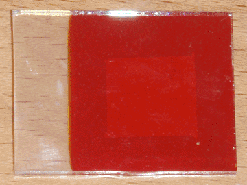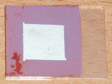

To better understand the nature of the compatibility problem between my conductive glass and copper oxide, I attempted to make a complete solar cell using just those two materials and silver paint. As before, the copper oxide film was full of pinholes, but I applied the back contact regardless. During this process, I used scotch tape to mask off the contact area. On removing the tape, large sections of the copper oxide peeled off, indicating that the problem lay in the weak adhesion between the two materials. Furthermore, when testing the cell, it produced a weak current in the opposite direction (glass positive) of the previous cell (glass negative). This indicates that there was no junction between the glass and the copper oxide, and a weak junction between the oxide and the silver paint.
To resolve both of these problems, I decided to introduce an intermediate layer of zinc oxide. I initially attempted to deposit this layer on the conductive glass by electroplating, but I had little success with this method. I then decided to take the simpler approach of spraying a piece of heated conductive glass with a solution of zinc chloride, which was successful. Heating was accomplished using my graphite hot plate, and the temperature was the same as was used for applying the initial conductive coating (400°C), indicating that the two layers could possibly be deposited sequentially. For this first cell I used approximately 5mL of 0.25M zinc chloride solution, but this is entirely un-optimized and will likely be revised in the future. A small piece of bi-layer (tin oxide/zinc oxide) glass was produced this way, then made into a solar cell using the same method as in the previous article. The completed cell can be seen at the top of the page.
The first thing I noticed was that the adhesion of the copper oxide improved remarkably. Only a single pinhole formed in the copper oxide layer as it was removed from the plating bath, likely from thermal shock, and during the masking process the tape only removed a small piece of copper oxide. Furthermore, the peeling occurred within the copper oxide layer itself, rather than it separating from the zinc oxide foundation. When tested under direct sunlight, this cell performed better in all aspects than its predecessor, indicating that pure zinc oxide may be preferable to AZO as the n-type semiconductor for this type of solar cell. With an active area of 1.7 square centimeters, it produced an open circuit voltage of 425mV and a short circuit current of 0.27mA, corresponding to a current density of 0.16mA per square centimeter.
One interesting characteristic of this cell was that its performance improved greatly after being exposed to light for ten to fifteen minutes. Within this timeframe, the voltage and current both improved by at least a factor of two, eventually reaching the maximum values specified earlier. This is likely due to the photoconductivity of zinc oxide, since I noticed the same effect in the previous cell, but to a much lesser extent. Unfortunately, beyond this point the voltage began to decrease, eventually settling to around 360mV. I believe this is due to the leakage current increasing as the zinc oxide becomes even more conductive from exposure to sunlight. This will likely be resolved later when I optimize the zinc oxide layer.
At this point, the only obstacle left is to develop an inexpensive back contact material to replace the silver paint currently in use. After that I will move on to optimization, and if I can produce a sufficiently efficient cell structure, I will then attempt to scale it up to the greatest extent that I am able to.