My first long-term vacuum tube goal has been achieved. I have successfully made a triode capable of voltage and power amplification, without any true high-vacuum equipment or any glassblowing equipment beyond a common plumbing torch.
Picking up where the previous article left off, I began with a pinch seal. I then clipped the internal leads to the correct lengths. The stepped heights are so that the components can be spot welded sequentially from top to bottom without the previous component interfering with the next weld. Before doing any spot welds on titanium, the mating surfaces must be ground to a bright finish. In the pictures below the plate and the grid are welded to the feedthroughs; the plate is made from 0.2mm titanium sheet, and the grid is made from the same 0.8mm titanium wire that the feedthroughs are made of. The filament assembly is then made and welded to the rest of the triode body, and the bridging connection at the bottom is clipped out. Like the previous diode, the triode has a large 0.1mm filament. The entire assembly is then soaked in acetone to remove any fingerprints. From this point on, only the external leads can be touched.
I then fused the evacuation stem onto an envelope I had prepared previously. Due to the design of the envelope, this went smoothly and did not require annealing. The constriction between the two pieces is to reduce the risk of implosion when sealing off the tube. The wider the gap that needs to be crossed by the collapsing glass, the greater the chance that it will bubble inward and ruin the tube.
The tube was then assembled by pre-heating both the envelope and the pinch seal assembly, fitting them together, fusing the seam with extreme heat (I used MAP gas rather than propane for this), then immediately wrapping the tube in ceramic wool. This entire process is time-critical, so no pictures could be taken.
After letting the tube cool for 30 minutes, I attached it to the pump manifold and began evacuating it. Once the pressure was below 15 millitorr, I put the oven on top and began the following bakeout schedule. I initially intended to bake the tube at 100W for a full hour, but this turned out to be too much heat, causing the tube to sag slightly inward and the titanium to turn blue from reacting with the low pressure air.
At this point, the tube was hot but not burning to the touch, and the pressure was down to 5-10 millitorr, so I lit the filament to drive out any trapped air and sealed the tube. Note the blue discoloration. While aesthetically pleasing, it is an indicator that the tube was overheated.
At this point I began testing the triode's electrical characteristics. As usual, due to the lack of a getter the initial characteristics were erratic. At low filament power and a plate current of around 50 microamps, it would behave like a triode. Above a certain threshold however, it would begin behaving like a thyratron and would peg out the microammeter. This threshold gradually increased, and eventually the tube stabilized. I began taking measurements.
I started by testing the grid response characteristics, as this would determine whether or not the tube was acting as a true triode or not. Once the tube stabilized, I recorded the following data for three different filament settings.
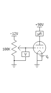
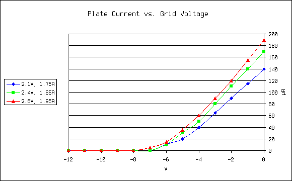
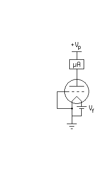
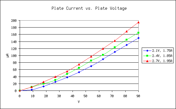
Although the overall current was disappointingly low, the grid response curves were very linear for grid voltages down to -4 volts. Within the linear region, the transconductance varied from 25 to 32 micromhos (microamps per volt) depending on filament power. Surprisingly, the hand-made grid (with very large gaps!) could block almost all of the plate current at -8 volts. I then tied the grid to the filament ground, and measured the diode characteristics of the tube. I hoped to find the saturation voltage, but it seems to lie somewhere beyond 90 volts. This is most likely due to the open nature of the filament, where one side has no plate to collect the space charge. Future tubes will use a cylindrical plate to eliminate this problem. Three curves were recorded for various filament settings.
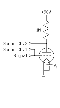
Next, I made an inverting amplifier. I input a 10KHz, 4 volt peak-to-peak sine wave with a -2 volt bias to the grid, and adjusted the filament power until the output waveform was centered around 45 volts. The output waveform was 20 volts peak-to-peak, meaning the amplifier had a voltage gain of 5, and no grid current could be detected. The voltage gain was constant for frequencies up to 10KHz, but dropped to 2 by 100KHz. There was no visible distortion of the waveform. On the oscilloscope screen below, the input waveform is on the bottom, with a scale of 2 volts per division. The output waveform is on top, with a scale of 20 volts per division.
Finally, I tested the tube qualitatively by replacing the resistor in the above circuit with a pair of headphones. I could hear the sound clearly, with no noise. I varied the bias voltage over the full range of my signal generator (-5V to +15V) and observed no change in the sound in either quality or volume, leading me to believe the linear grid response continues well into positive grid voltages. I then disconnected the grid from the signal generator and heard a faint hum. Touching my finger to the grid lead greatly amplified this hum, which I believe was the 120Hz flicker of the fluorescent lights overhead. Holding my other hand near a grounded object reduced the volume of the hum, and touching the grounded object muffled it severely. The grid appears to be very sensitive.
I plan to continue testing this triode for stability. The diode made previously still works and has the same characteristics as when it was first tested. In the near future I plan to make an improved triode and a power rectifier tube. In the far future, my next long-term goal is to build a cathode ray tube.