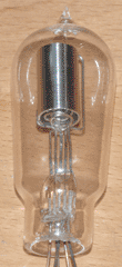
Triodes can amplify a signal, but to efficiently modulate one signal by another (such as in a radio transmitter), an amplifier with multiple grids is necessary. For this purpose I built a tetrode, thus completing my second major vacuum tube goal. Its layout is identical to that of my earlier triode, other than the size of its components and the fact that it has two grids. The construction process can be seen below.
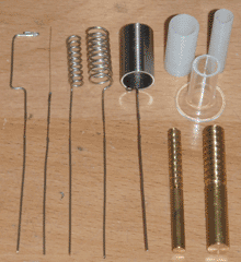
The grid winding was done in the same manner as the triode; the inner grid was wound on the same mandrel used previously, and a larger mandrel was turned on the lathe for the outer grid. It is important to note that the outer mandrel has a left-handed thread, so that the two grids cross each other and form a mesh between the filament and the plate. If the grids were both right-handed, there is a possibility that the outer grid could hide behind the inner grid, reducing its effect on the electron flow.
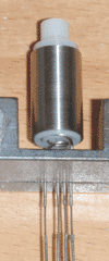
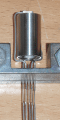
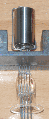
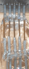
The alignment of the grids and plate was by far the most difficult part of the construction process. An earlier tetrode attempt was aligned by hand, but this was extremely time-consuming. To speed up the process, I made two Delrin spacers which take up the empty space between the grids and plate. This allows for the majority of the tube internals to be fit together before they are clamped in place. Once the tube internals were aligned and clamped, I made the pinch seal using my crossfire torch and improved wire holder. The alignment of the feedthroughs is superb as a result, and can be seen above. I then evacuated, baked, and sealed off the tube in the usual manner.
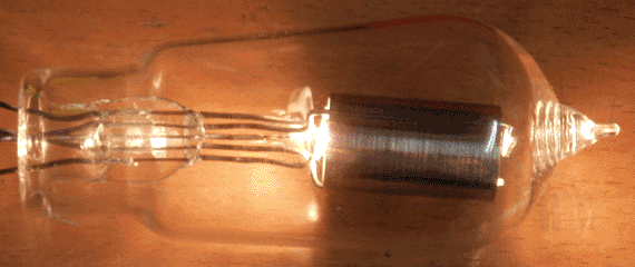
Despite being well put together, the tetrode endured a fair amount of abuse. I accidentally dropped it about a foot onto the surface of my workbench, which is the cause of the crooked internal structure. This caused some of the components to short together, but luckily I was able to knock it back into proper alignment. I'm glad this happened, however; it revealed a need for better internal support structures in future vacuum tubes. The relatively large half-inch titanium tubing used for the plate has enough inertia that even a slight bump is enough to shift it out of place.
Another problem that occurred was due to the filament material I used. I anticipated that having two grids would severely limit the electron flow, so I built the tube with a 0.15mm filament to provide better emission. This is larger than was used in any previous tube, and the new filament wire contained a large amount of occuluded gas, despite being briefly flashed to white-hot while on the pump. This repeatedly caused the tube to stop functioning during initial testing due to ionization. Fortunately, titanium is a superb getter material and can be reused a large number of times. By heating the plate immediately after running the filament at high temperature, I was able to clean up the aforementioned gas.
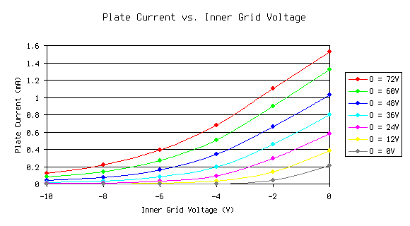
Once the tube was stable, I began measuring its characteristics. Thanks to Materials and Techniques for Electron Tubes by Walter H. Kohl, I was able to determine the proper filament current for any desired filament temperature. For all charts below, the filament current was set to 2.5A in order to effect a filament temperature of approximately 2350K. This is somewhat low, but I discovered early on that increasing the filament temperature did little to increase the plate current, at least when operating the tube as a tetrode. The grids are by far the most limiting factor. The plate voltage was kept constant at 72V as well, to avoid the need for a 3-dimensional graph. In the graph below, the inner grid voltage is varied between -10 and 0 volts, at various settings of the outer grid voltage (O). It is apparent that the inner grid has a far greater effect on electron flow than the outer one.
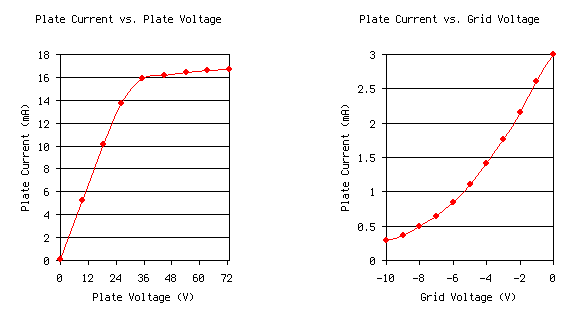
Alarmed by the low values of plate current, I configured the tube as a diode and a triode by connecting one or both grids to the plate, starting with the outer grid. I then recorded the characteristic curves below. It is immediately apparent that as more grids begin influencing the electron flow, the current drops dramatically. This could likely be resolved by operating the tube at higher plate voltages, however.
Like most other tubes, I will give this tetrode a waiting period to ensure its stability before using it in a circuit. Beyond that point I will probably attempt to make another power triode, then start working toward my final goal of building a cathode ray tube. It is becoming abundantly clear that fairly complex vacuum devices can be made with consumer-grade and improvised equipment, and I am interested in seeing how far I can go with this.