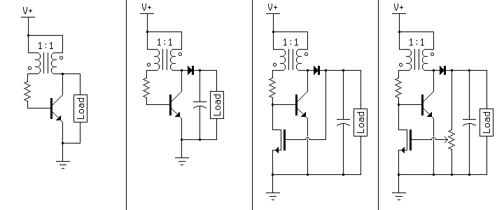
The joule thief is a blocking oscillator used as a boost converter. The normal output is a series of current pulses, but a diode and a capacitor can turn this into a steady DC voltage. This voltage is highly load-dependent however, so a MOSFET can be used as feedback to turn off the oscillator when the output reaches its threshold voltage. The addition of a potentiometer allows the output voltage to be set arbitrarily, so long as it exceeds the threshold voltage of the MOSFET. The diagram below shows this progression.
These are generic schematics, however. A specific example is shown below. The following circuit boosts the voltage from a single 1.5V battery (AAA, AA, C, D, etc.) to between 2.6 and 10 volts.
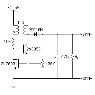
The transformer in this case is a ferrite toroid about an inch in diameter, with three turns on each winding. More turns will work, but this brings the frequency of the oscillator into the audible range, and the circuit whines under load. The other parts are simply what I had on hand. Any power NPN transistor and any MOSFET will work, and the RGP10M is completely unnecessary for the voltage and current involved here; I tried a 1N4148 in its place later and had the same results. The values of the resistor and capacitor are fairly important, however. The base resistor sets the current draw for the oscillating transistor and, combined with the inductance of the transformer windings, sets the frequency of the oscillator. I found 100 ohms to be a good value. Lower values increased current draw without increasing useful power output, and higher values reduced power output without any increase in efficiency. The capacitor should be as large as possible. Too small of a capacitor will result in voltage spikes being sent to the gate of the feedback MOSFET, destroying it. The potentiometer's resistance should be as high as possible as well, since the MOSFET doesn't draw any current.
I built three versions of the above circuit and tested the output voltage under load. The first has no feedback, the second has the output connected directly to the gate of the MOSFET, and the third is the complete circuit with the potentiometer set to regulate the output at 5 volts.
| Load (Ohms) | Unregulated (V) | Gate Regulated (V) | Pot. Regulated (V) |
|---|---|---|---|
| 100 | 4.2 | 2.6 | 4.1 |
| 200 | 5.9 | 2.6 | 4.9 |
| 300 | 6.9 | 2.6 | 5.0 |
| 400 | 8.0 | 2.6 | 5.0 |
| 500 | 8.7 | 2.6 | 5.0 |
| Open Circuit | 36.5 | 2.6 | 5.0 |
The regulated circuits appear to be very stable, and gain the ability to operate open-circuit without the voltage climbing until component failure (in my case the capacitor was rated for 35V, so I assume it began to leak). I looked at the output with my oscilloscope as well, and the ripple was negligable with a 500 ohm load; typically below 50mV, at around 40KHz. A second filtering stage could eliminate this easily, if a very clean DC supply was needed (e.g. for a microcontroller). The ripple only began to increase when the circuit was overloaded and the output sagged below its set voltage. Finally, I connected the circuit to my DC power supply (I had been running it off of a D battery) and varied the input voltage. Unfortunately, the output does vary with a change in input. I set the input to 1.5V and the output regulation to 5.00V, with no load. I then lowered the input to 0.75V and the output had dropped to 4.40V. Beyond this point the output dropped quickly, and the circuit failed to oscillate below 0.50V. Although somewhat disappointing, a 12% change in output for a 50% change in input isn't too bad.
The regulation also has the effect of making the input current proportional to the load. With no load, this circuit uses practically no power, as the oscillator is turned off most of the time. In this idle state, the only waste current is through the base resistor, which is less than 10mA. This is a huge advantage over using something like a linear regulator where the output voltage is limited after the fact, with the oscillator running full bore 100% of the time. Interestingly, this circuit has a mechanical analogue in the form of the hit-and-miss engine, which operates on a similar principle.
At 1.5V the power output is fairly limited, but this circuit is more of a generic boost converter than a true joule thief. For example, with a higher input voltage, a higher-VCE power transistor, and a 1M+ resistor above the potentiometer, this could be used as a compact high voltage supply for nixie tubes. I would have attempted this, but I didn't have any suitable transistors.