Although I still lack a fully functional induction heater, I decided to build a diode anyways. It is based on the three-part construction method used for the large glow tube and the light bulb featured in the bakeout oven article. Both of these tubes still work, so this construction method seems very reliable. Due to this tube having a vertical filament (to avoid hot spots on the glass) the electrode assembly is more complicated than in previous tubes, and is shown in the diagram below.
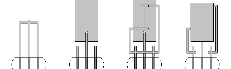
First, the pinch seal is made with a hairpin-style lead assembly made of 0.8mm titanium wire. Next, the leads are separated and cut to length, and the anode (a long strip of 0.2mm titanium sheet) is spot welded onto the center lead. Then, a G-shaped filament assembly is spot welded onto the side leads. Finally, the anode is bent over the filament so that it is close on both sides, and the short circuit between the two filament leads is clipped out. The components are then bent into their final positions, making sure that there are no accidental shorts. The assembly is then soaked and stirred in acetone to remove any fingerprints.
Once the tube was assembled, it was held at a vacuum of 15 millitorr (higher than usual due to issues with the vacuum manifold) and baked out for an hour, with the peak temperature being just below the softening point of the glass (determined by trial and error). The bakeout schedule was as follows:
When I removed the bakeout oven from the tube the glass was hot but not burning to the touch. I tried to heat the anode with the partially completed induction heater, but the high resistivity of titanium made it ineffective. I lit the filament to drive out any gases trapped inside, but noticed no change on the vacuum gauge when I did so. Despite using a large 0.1mm filament, I didn't want to run it for too long before sealing the tube off, so I didn't test the tube while it was on the pump. The seal-off went well, and as soon as the tip was cool I began measuring the tube's characteristics. A picture of the setup can be seen below.
Much like the first diode, the characteristics were erratic but then stabilized as the filament consumed what it could of the remaining gases in the tube. Emission continually increased until it was fairly stable, at which point I recorded the anode current for various filament currents and anode voltages. I then let the tube sit overnight, and tested it again the next day. To my surprise, despite the lack of a getter, the tube worked the next day and its characteristics had even improved slightly overnight. I recorded its characteristics again, and they can be seen below. The three curves correspond to three different filament settings, which can be seen on the right.
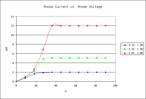
This diode seems to have very well-defined characteristic curves, the shapes of which match those of commercial diode tubes. Of all of the above filament settings, only the lowest seemed safe for long term operation. I could be mistaken, however.
I then went on to test the dynamic characteristics of the diode. I disconnected the 90-volt battery and in its place I connected my signal generator to the anode, through a resistor. I set my signal generator to output a 10 volt (peak-to-peak) sine wave at 10KHz. I then connected my oscilloscope to the signal generator and to the anode. The pictures below show the results for two values of the resistor. The pictures on the left are for filament values of 1.3V and 1.4A (non-emitting), and the pictures on the right are for filament values of 2.1V and 1.8A (emitting, following the lowest curve on the graph above). I chose 10KHz as the input frequency because above this the diode's conductance began to drop off, and it became non-functional (at least at the low voltages present) by 100KHz. In all of the pictures, the signal generator output is on top, and the anode voltage is on the bottom.
R = 100K
Even at these low voltages, the functionality of the diode can be observed. Some improvements are needed, however. First, some form of getter must be made, to spare the filament from having to clean up residual gases. Next, a structure which centers the electrodes in the tube envelope must be developed, as the glass does get hotter on one side than on the other due to the electrode assembly being slightly tilted. This will also make tube construction easier, as keeping the pinch seal centered while fusing it to the envelope is always tricky when done by hand. Finally, I will experiment with nickel wire for the tube leads, since titanium is impossible to solder with conventional fluxes and forms an insulating oxide layer which makes mechanical connections tempermental. I will continue testing this diode for stability, and will now attempt to make a triode.