The coherer is one of the simplest types of radio wave detectors. It consists of a tube of metal filings with an electrical connection at either end. It normally has a high resistance, but when hit by a strong radio signal the resistance drops by multiple orders of magnitude. It can then be reset to a high-resistance state with a light tap, to break up or "decohere" the filings in the tube. I made one using some 5mm glass tubing, filings from a piece of steel, and some scrap galvanized steel rod. It can be seen above.
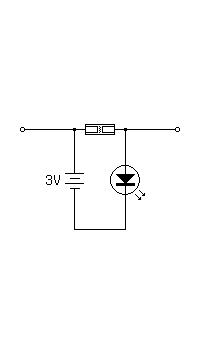
In making this coherer, I found that the gap between the electrodes must be fairly small (1-3mm) and the filings must be as fine as possible. Once I overcame these issues, the coherer worked well. I connected it in series with an LED and two AA batteries, and it could be triggered using the spark box described in the previous article. Unfortunately, the high voltage module in the box failed again during testing, so I will have to find a better module more suited to driving a spark gap. Below is a picture of the circuit; the screwdriver was used to tap the coherer to reset it.
I initially tested this circuit with no antenna on either the spark box or the coherer, and it only had a range of about a foot. I then added an 18 inch alligator clip lead to either end of the coherer (green in the above picture), and used more of the galvanized rod used earlier as an antenna for the spark box. This increased the range to around 10 feet. I'm sure this could be optimized further, though. Finally, I measured the resistance of the coherer and found it to be between 100K and 500K in the "off" state, and between 30 and 60 ohms in the "on" state. The spark box with its antenna can be seen below. The gap is small because at this point the high voltage module had already partially failed, and could only produce a very short spark.